ECE 358 Computer Networks
Table of contents
2. Link Layer
Networking layer 2
nodes: hosts and routers
links: communication channels between adjacent nodes
- wired
- wireless
- LANs
frame: layer-2 packet encapsulating (layer 3?) datagram
Error Detection
Parity Checking
single bit parity: detect single bit error
- add bit so that # of 1’s is even/odd for even/odd parity
2D bit parity: detect and correct single bit errors
- parity of each row/col
Cyclic redundancy check (CRC)
Setup:
- data \(D\) of \(d\) bits
- choose CRC \(R\) of \(r\) bits
- choose generator \(G\) of \(r + 1\) bits
Idea:
- \(DR\) should be exactly divisible by \(G\) (mod 2)
- receiver knows \(G\)
- detect all burst errors less than \(r + 1\) bits
Calculate CRC: \(R = \text{remainder}(\frac{D 2^r}{G})\)
Multiple access protocols
Apply to shared (broadcast) links
Ideally:
- when one node wants to transmit, it can send at the full link rate \(R\)
- when \(M\) nodes want to transmit, each can send at average rate \(\frac{R}{M}\)
- decentralized (no master, clock synchronization)
- simple (plug and play, no configuration)
3 types of MAC (medium access control) protocols:
- channel partitioning (avoids collisions)
- random access (allows collisions)
- taking turns
Channel partitioning MAC protocols
time division multiple access (TDMA)
- nodes get access to channel in rounds
- adv: fair, collision free
- disadv: waste bandwidth, unnecessary waiting
frequency division multiple access (FDMA)
- divide channel into frequency bands
- same adv/disadv as TDMA
Random access protocols
slotted ALOHA
- frames, slots same size
- if collision
- all nodes detect collision
- node retransmits in each subsequent slot with probability \(p\)
- adv: single node full channel rate, decentralized, simple
- disadv: collisions waste slots, idle slots, clock sync
- best: 37% useful transmissions
pure (unslotted) ALOHA
- no synchronization
- transmit frames immediately
- collision probability increases
- best: 18% useful transmissions
carrier sense multiple access (CSMA)
- listen before transmit
- if channel idle, transmit entire frame
- if channel busy, defer transmission
- collisions can still occur - propagation delay means nodes may not hear each other’s transmission
CSMA/CD (collision detection)
- collision detection
- easy in wired LAN: measure signal strengths, compare transmitted and received signals
- difficult in wireless LAN: received signal strength overwhelmed by local transmission strength
- if NIC detects another transmission while transmitting, abort and sen d jam signal and enter exponential backoff (up until value of 10 times)
- medium sensing for 96 bit times
- jamming signal length is 48 bits - enough energy for collision detection
- efficiency \(\rightarrow 1\) as \(t_{prop} \rightarrow 0\) and \(t_{trans} \rightarrow \infty\)
CSMA/CA (collision avoidance)
- if channel idle: transmit frame
- if channel busy:
- start random backoff
- while channel busy, timer counter frozen
- timer counts down while channel idle
- transmit when timer expires
- if no ACK, increase random backoff interval
Taking turn protocols
polling: master polls slaves nodes
- no collisions and empty slots
- disadv: polling overhead, single point of failure
token passing: control token passed from between nodes
- disadv: token overhead, single point of failure (token)
MAC addresses and ARP
MAC address: used locally to get frame from one interface to another interface
- each adapter on LAN has unique LAN address
- allocation admistered by IEEE, manufacturer buys portion of MAC address space
- MAC address is portable - can move LAN card from one LAN to another
address resolution protocol (ARP)
- determines an interface’s MAC address knowing its IP address
- plug-and-play
- ARP table: each IP node (host, router) on LAN has a table
- <IP address, MAC address, TTL>
- TTL (time to live): time after which address mapping is forgotten
ARP on same LAN
- A wants to send to B
- B’s MAC address not in A’s ARP table
- A broadcasts ARP query with B’s IP address, include destination MAC address FF-FF-FF-FF-FF-FF
- B receives ARP packet, replies to A with its MAC address
- A saves info into ARP table
ARP routing to another LAN
- first hop router forwards A’s packet to B
Ethernet
Topologies
bus: all nodes in same collision domain
star: prevails today
- active switch in center
- no collision between nodes
Ethernet frame
- preamble: 7 bytes + 1 byte (wakeup procedure to sync receiver and sender clock rates)
- addresses: 6 byte source and 6 byte destination MAC address
- on receiving a matching dest address or broadcast address, passes data to network layer
- otherwise discard frame
- type: higher layer protocol (usually IP)
- CRC: if error detected, drop frame
Reliability
connectionless: no handshaking between sender and receiver
unreliable: receiving NIC doesn’t send ack or nack
- dropped data recovered only if sender uses higher layer protocol (TCP)
Uses unslotted CSMA/CD with binary backoff
Ethernet switch
- link layer device
- store and forward ethernet frames
- examine incoming frames, selectively forward
- transparent: hosts unaware of presence of switches
- plug-and-play: no config
- multiple simultaneous transmissions
- hosts have dedicated connection to switch
- each link is own collision domain
- full duplex
switch table
- <MAC address of host, interface to host, TTL>
- like routing table
- switch learns which hosts can be reached through which interface
- on frame receive, switch learns location of sender - update switch table
- if destination entry found, forward to that interface (as long it’s not the incoming interface)
- otherwise flood - send to every interface (switch still does not learn MAC address until it sends something back)
Wireless LAN (WLAN/Wifi)
Wireless access point (AP) is physically connected to a router
- AP has physical layer and a link layer above that that converts Wifi to ethernet
basic service set (BSS): an AP and the hosts connected wirelessly to the AP
hidden terminal problem:
- C transmits frame to B
- A is unaware of C’s transaction (only sees B)
- if A transmits, will collide with C’s transaction at B
- C is hidden from A
- solution: CSMA/CA
exposed terminal problem:
- A transmits to D
- B sees A, knows that it is transmitting
- B can transmit to C, but it doesn’t because of A’s transmission
- loss of bandwidth
- B is exposed to A’s transaction
- no solution provided so far…
Modes of operation
distributed coordination function (DCF)
- no need for AP - if there is an AP, it acts like an ordinary node and just provides connectivity to the internet
- nodes make their own decisions to transmit
- handshake mode, w/out handshake mode
point coordination function (PCF)
- AP is the controller in the BSS and decides who and when of transmission
- no contention for medium access
- waste of bandwidth if scheduled node has no traffic
Distributed coordination function (DCF) with handshake
dotRTSThreshold: MAC management holds this variable
- if frame length >= dotRTSThreshold, use DCF with handshake
- long frames - want to reduce probability of collision
- otherwise, use DCF without handshake
Control frames:
- RTS (request to send)
- 20 bytes
- duration is how long the sender wants to use the medium for
- CTS (clear to send)
- 14 bytes
- duration is how long the sender wants to use the medium for
WLAN MAC: CSMA/CA via 2 techniques
- physical level carrier sensing (hardward)
- virtual carrier sensing:
- integer variable in each node NAV (network allocation vector) indicates whether a nearby node is likely to be transmitting
- NAV > 0: most likely another node is transmitting
- NAV = 0: no one nearby is transmitting
NAV in detail
- all nodes which receive RTS and CTS (and DATA) update NAV as follows
- at each micro second, decrease NAV if NAV > 0
- if a frame with duration \(d\) is received, NAV=max(\(d\), NAV)
- 4 timing intervals:
- physical level
- SIFS: short inter frame space (10 microsec)
- how long to wait before sending CTS, DATA, ACK
- aSlot (20 microsec)
- SIFS: short inter frame space (10 microsec)
- MAC level
- PIFS: priority IFS (SIFS + aSlot)
- DIFS: distributed IFS (PIFS + aSlot)
- how long to wait (and medium idle and NAV = 0) before sending RTS
- SIFS < PIFS < DIFS
- no one can transmit between RTS - CTS - DATA - ACK
- duration variable of RTS includes time to send CTS + DATA + ACK and their included SIFS times
- physical level
Distributed coordination function (DCF) without handshake
- no RTS/CTS
- NAV is still used - nodes must process RTS/CTS of others
- sender wait for DIFS before sending DATA
- receiver wait for SIFS before sending ACK
Point coordination function (PCF)
- if AP finds medium idle for PIFS, transmit beacon frame
- beacon contains CFPMaxDuration field (CFP: contention free period)
- nodes receiving beacon update NAV and don’t transmit unless asked by AP
- after beacon, AP waits for PIFS before transmitting one of
- DATA
- unicast or broadcast
- PIFS before sending data again
- CF poll (contention free)
- user can send after SIFS
- if user does not have data, it sends a null DATA frame
- DATA + CF poll
- polled user receives data from AP and sends data to another user
- ACK
- CF end
- signifies end of CF period, receiving nodes set NAV=0
- DATA
- if ACK not received from AP, user waits until it is polled again
Wifi frame:
- AP converts between Wifi and ethernet frames
- A1: destination of the wifi link
- A2: source transmitter of the wifi link
- A3: source/destination - the node that the AP is connected to (usually a router)
3. Network Layer
- transports transport layer segments between hosts
- encapsulates segments into datagrams
- in every host and router
Key functions
forwarding: move packets from router’s input to appropriate router output
routing: determine route taken by packets from source to dest via routing algorithms
- the output of routing algorithm is a forwarding table (<IP address, interface>)
Key router functions
- run routing algorithm (software)
- forward datagrams (hardware)
Input port functions
- line termination: physical layer
- link layer receive
- lookup in forwarding table in input port memory, forwarding, queueing
queueing
- fabric slower than input ports combined
- HOL (head of line) blocking: queued datagram at front of queue prevents others in queue from moving forward
Switching fabric
Transports packet from input buffer to appropriate output buffer
memory switching
- traditional computer, switching under direct control of CPU
- packet copied into system memory
- 2 bus crossings per datagram
bus switching
- input port memory to output port memory via shared bus
- contention for shared bus (1 transmission at a time)
- 1 bus access per datagram
interconnection network switching
- like a grid
Output ports
buffering: required when datagrams arrive from fabric faster than transmission rate
- recommended size with RTT (round trip time), \(C\) link capacity, \(N\) flows user buffer size \(\frac{RTT \times C}{\sqrt{N}}\)
scheduling discipline: choose among queued datagrams for transmission
Switch vs router
| Routers | Switches | |
|---|---|---|
| Layer | network layer device | link layer device |
| Store and forward | yes | yes |
| Forwarding table | yes (via routing algo) | yes (learned) |
| Traffic isolation | yes | no (broadcast seen at all interfaces) |
| Processing delay | slower | faster |
| Require config | yes | no (plug and play) |
| Broadcast storm | no | yes |
IP datagram format
TODO
Header checksum
Example calculation at the sender:
IP header (in hex) with checksum set to 0000:
                         csum
4500 0073 0000 4000 4011 0000 c0a8 0001 c0a8 00c7
Step 1: add all 16 bit clocks of the header
result = 2 479c- add carry (2) to the rest to get
temp = 479e
Step 2: take 1’s complement of temp to get checksum
checksum = b861
Step 3: put this in the header
Example calculation at the receiver:
Assume header received without bit error
                         csum
4500 0073 0000 4000 4011 b861 c0a8 0001 c0a8 00c7
Step 1: add all 16 bit blocks of the header
result = 2 fffd- add carry (2) to the rest to get
temp = ffff
Step 2: take 1’s complement of temp
result = 0000
Step 3: if result == 0000 the no error. Otherwise bit-error, drop packet
IP fragmentation
Network links have MTU (maximum transmission unit): largest possible link-level frame.
Large IP datagrams get divided into multiple datagrams.
- reassembled at final destination
- IP header bits used to identify and order the fragments
- offset field in header, which are multiples of 8 bytes
IP addresses
In IPv4 IP addresses are 32-big long
L2 switches and hubs do not have IP addresses
End-devices generally have 1 IP address each (laptop, desktop, server)
Routers have multiple IP addresses, 1 or more for each physical interface
Network prefix
All IP addresses on the same link have a common portion in the most significant bits, known as network prefix.
Example:
     prefix      host ID
IP1: x.y.z.10101 001
IP2: x.y.z.10101 010
IP3: x.y.z.10101 011
IP4: x.y.z.10101 100
Classful addressing
Characterized by fixed length prefixes.
- class A: addr begins with
0and prefix is 8 bits - class B: addr begins with
10and prefix is 16 bits - class C: addr begins with
110and prefix is 24 bits
Fixed number of networks and addresses per network
Classless addressing
CIDR (classless interdomain routing): prefix is arbitrary length
Example: 200.23.16.0/23 specifies that 200.23.16.0 is the prefix of length
23
For a network prefix of 129.97.0.0/16, the router represents it as
129.97.0.0/255.255.0.0 where 255.255.0.0 is a mask.
Network ID
network ID appear in routing tables, individual host IPs do not
broadcast address used to perform IP-level broadcast
Example: given a network 10.2.5.16/28
- first address is
10.2.5.16and is the network ID - last address is
10.2.5.31and is the broadcast address
Public and private IP addresses
Public:
- globally unique
- recognized by every router
- any host can open a TCP connection
Private:
- unique within an org
- only recognized by routers within the org
- host outside the org cannot open TCP connection
- IP reuse and added security
Packet forwarding
packet forwarding: relay packets from one physical interface to another by routers
Next hop calculated with destination address and routing table.
- routing table entries learned through routing protocols
- for a destination
ip_destand given entry ofip, mask, match occurs whenip_dest && mask == ip && mask
Many matches can occur in a routing table. In this case find the entry with longest prefix (smaller pool of possible destination IPs).
DHCP
dynamic host configuration protocol: allow host to dynamically obtain IP address from network server
- host broadcasts
DHCP discovermsg (optional) - DHCP server responds with
DHCP offermsg (optional) - host request IP with
DHCP requestmsg - DHCP server sends IP address with
DHCP ackmsg. This also returns:- IP address of first-hop router
- name and IP of DNS server
- network mask
DHCP works on UDP.
Address aggregation (supernetting)
If router can reach:
192.168.0.0/24
192.168.1.0/24
192.168.2.0/24
192.168.3.0/24
Instead of advertising all 4 networks, advertise 1 address and say it can reach
192.168.0.0/22
NAT
NAT (network address translation): local network uses one IP address in view of outside world.
- just need one IP address for all devices
- change address in local network without notifying external
- devices not externally accessible
NAT does public-private address/port translation.
- uses 16 bit port number field
- controversial since higher than layer 3
NAT traversal problem
External wants to connect to server with private IP 10.0.0.1 (can’t use it as
dest addr).
solution 1: statically configure NAT to forward incoming requests at some port to the server
solution 2: universal plug and play (UPnP). Allow server to learn public IP address and add/remove port mappings
solution 3: relaying (Skype)
- server establishes connection to relay (which is outside the LAN)
- external client connects to relay
- relay bridges packets between connections
ICMP
ICMP (internet control message protocol): used by hosts and routers to communicate network level information
- error reporting: unreachable host, network port, protocol
- echo request/reply (ping)
- carried in IP datagrams
Traceroute and ICMP
- source sends series of UDP segments to dest
- first set has TTL = 1, second set TTL = 2, etc.
- unlikely port number
- when n-th set of datagrams arrives at n-th router
- router discards datagrams
- sends source ICMP messages including name of router & IP address
- when ICMP messages arrive, source records RTTs
- stopping criteria:
- UDP segment eventually arrives at dest host
- returns ICMP “port unreachable”
- source stops
IPv6
32-bit address space soon to be completely allocated
datagram format:
- fixed-length 40 byte header
- no framentation
- no checksum to reduce processing time at hops
- options allowed, but outside of header
- ICMPv6
- additional “packet too big” message
Transition from IPv4 to IPv6
- not all routers can be upgraded simultaneously
- tunneling: IPv6 datagrams carried as payload in IPv4 datagram
Routing algorithms
Classification
global vs decentralized information:
global: all routers within autonomous system have complete topology
- link state algorithms
decentralized: router knows physically connected neighbours
- iterative process of computation, exchange info with neighbours
- distance vector algorithms
static vs dynamic:
static: routes change slowly over time
dynamic: routes change more quickly
- periodic update in response to link cost changes
Autonomous system (AS)
A set of routers under a single technical admin, using an interior gateway protocol and common metrics to route packets within the AS.
Uses exterior gateway protocol to route packets to other AS’s.
Identified by a 16-bit ID AS-number.
Intra AS routing:
- RIP: routing information protocol (distance vector)
- OSPF: open shortest path first (link state)
Inter AS routing:
- BGP: border gateway protocol
Distance Vectors
\(D_x(y)\) is the estimate of least cost from \(x\) to \(y\)
- \(x\) maintains distance vector \(D_x=[D_x(y) : y \in N]\)
- \(N\) is the set of all nodes in the network
Node \(x\)
- knows cost \(c(x, v)\) for each neighbour \(v\)
- maintains neighbours’ distance vectors. For each neighbour \(v\), \(x\) maintains \(D_v = [D_v(y) : y \in N]\)
Algorithm:
- occasionally each node sends its own distance vector to neighbours
- when \(x\) receives new distance vector from neighbour it updates its own distance vector as per Bellman-Ford equation: \(D_x(y) = \text{min}_v\{c(x, v) + D_v(y)\} \text{ for each node } y \in N\)
- the estimate should converge to the actual cost
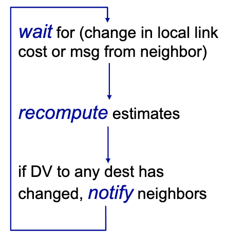
Each local iteration caused by:
- local link cost change
- DV update message from neighbour
Each node notifies neighbours only when its DV changes
Operation of node:
Two node instability problem:
The algorithm can get stuck in a loop when node X goes down. Solutions:
- split horizon: if node B learns about a path to X from A, B does not tell A about it
- poisoned reverse: if A tries to route to X via B, A tells B that it has an
infinity-cost path to X when the (X, A) link is broken
- enables B won’t try to forward the packet to X via A
Does not solve three-node or four-node instability.
RIP (routing information protocol)
Distance vector algorithm
- distance metric: # hops (max = 15)
- each link has cost 1
- DVs exchanged with neighbours every 30s
- each advertisement: list up to 25 destination subnets
Link failure: if no advertisement heard after 180s, neighbour declared dead
- routes via neighbour invalid
- new advertisement sent
- propagates quickly
- poison reverse used to prevent ping-pong loops (infinite distance = 16 hops)
RIP table processing
RIP routing tables managed by app-level process called route-d.
Advertisements sent in UDP packets.
OSPF (Open shortest path first)
- link state algorithm
- each node has topology map
- advertisements carry one entry per neighbour
- advertisement flooded to entire AS
Overview:
- each router learns complete topology of network within AS via flooding of OSPF advertisement messages
- use Dijkstra’s algo to compute shortest paths between all pairs of nodes
- for a given source/dest pair, find next hop from shortest path
Advanced features:
- all messages authenticated
- multiple same-cost paths allowed
Hierarchical OSPF: TODO
BGP (Border gateway protocol)
Forwarding table configured by both intra AS and inter AS routing algorithms.
BGP provides each AS a means to:
- eBGP (AS external): obtain subnet reachability info from neighbouring AS’s
- iBGP (AS internal): propagate reachability info to all AS-internal routers
- determine good routes to other networks based on reachability info
BGP messages: exchanged between peers over TCP
- OPEN: open TCP to peer and authenticate sender
- UPDATE: advertise new path or withdraw old
- KEEPALIVE: keeps connection alive in absence of UPDATES, also acks OPEN
- NOTIFICATION: report errors in previous message, also used to close connection
BGP session: between two BGP routers
- advertise paths to different network prefixes
- on advertisement of a prefix, the AS promises it will forward datagrams toward that prefix
Path attributes: advertised prefix includes BGP attributes (prefix + attributes = route)
- AS-PATH: contains AS’s through with prefix advertisement has passed
- on ties, router selects a route based on shortest AS-PATH
- NEXT-HOP: indicates specific internal-AS router to next-hop AS
- router uses OSPF to find shortest intra AS path to the NEXT-HOP and saves in the forwarding table
- gateway router can use import policy to accept/decline route advertisement
- ex. never accept a route that went through AS 217
Hot potato routing: on equal AS-PATH length, choose route with closest NEXT-HOP using OSPF
BGP algorithm:
- router becomes aware of prefix via BGP advertisements
- determine router output port for prefix
- use BGP route selection to find best inter-AS route
- use OSPF to find best intra-AS route leading to best inter-AS route
- router identifies router port for that route
- enter prefix-port entry in forwarding table
AS export policy: which routes it will advertise
- to a customer: all routes
- to a peer or service provider:
- routes to all its own subnets and to customers’ subnets
- but not to subnets learned from other providers/peers
4. Transport Layer
Provides logical communication between app processes running on different hosts.
Runs on end systems:
- send side: break app messages into segments, passes to network layer
- receive side: reassemble segments into messages, passes to app layer
UDP (user datagram protocol): no reliability (RIP, SNMP)
TCP (transmission control protocol): reliable data delivery (FTP, HTTP)
Ports
Programs use port numbers to address other programs.
Ports identified by 16-bit ID. \(2^{16}\) UDP ports and \(2^{16}\) TCP ports.
3 addresses:
- MAC addr for 1 hop comm
- IP addr for multi-hop comm
- ports for app-app comm
Multiplexing/demultiplexing
multiplexing at sender: handle data from multiple sockets, add transport header
demultiplexing at receiver: use header info to deliver segments to correct socket
- use IP address and port number to direct segment to appropriate socket
connectionless demultiplexing: UDP segment directed only based on dest address and port
connection oriented demux: TCP socket identified by source/dest address/port
UDP
“best effort” service
Segments can be:
- lost
- delievered out of order
Add reliability at app-layer
Connectionless:
- no handshake
- each segment handled independently
Uses:
- streaming multimedia
- DNS
- SNMP
Reliable data transfer
- Automatic Repeat Request (ARQ) protocol
- requires feedback from receiver (ack)
- sequence numbers used to solve out-of-order and duplicate packets
- timers used to solve lost packets
Stop and wait
- send packet, start timer, wait for ack
- if timer runs out, retransmit
Duplicate packets and acks will be discarded.
Performance is bad, low utilization of link.
Pipelined protocols
Increases utilization.
Sender can have up to N unacked packets in pipeline
go back N
- window of up to N consecutive unacked packets
- receiver only sends cumulative ack: doesn’t ack if there’s a gap
- sender has timer for oldest unacked packet
- on timer expires, retransmit all unacked packets
- out of order packet:
- discard (no buffer)
- re-ack packet with highest in-order seq #
- duplicate ack discarded by sender
selective repeat
- window of up to N consecutive packets
- receiver sends individual ack for each packet
- maintain timer for each unacked packet
- on timer expire, retransmit only that unacked packet
- buffer out-of-order packets as needed for eventual in-order delivery to upper layer
- window size should be at most half the sequence # space
- because then advancing the window by a full window size will not lead to ambiguity of accepting a sequence # that could be from current window or next window
TCP
- connection oriented: handshake initializes sender and receiver
- point to point: 1:1 sender to receiver
- reliable, in order byte stream
- full duplex
- pipelined
- flow control: sender will not overwhelm receiver
Header
Sequence number and ack number fields counted by # of bytes (not segments).
sequence numbers: byte stream “number” of first byte in segment’s data
ack number: sequence # of next byte expected from other side
- cumulative ack
Receiver generally buffers out-of-order segments.
Piggybacking
ACK for client-to-server data carried in data segment from server-to-client.
Eliminates need for separate ACK messages.
TCP fast retransmit
- timeout period relatively long
- instead, detect lost segments via duplicate ACK
- if segment lost, there will likely be many duplicate ACKs
fast retransmit:
- if sender receives 3 ACKs for same data, resend unacked segment with smallest
seq #
- likely the unacked segment was lost, so don’t wait for the existing timeout
TCP flow control
Receiver controls sender so sender won’t overflow receiver buffer by transmitting too fast.
Receiver advertises free buffer space by including rwnd (receiver window)
value in TCP header. RcvBuffer is total buffer size.
- sender limits window to receiver’s
rwndvalue
TCP handshake
TCP fields:
- connection request (SYN)
- initial sequence number (ISN)
- acknowledgement (ACK)
- receive window size
3 way handshake
- SYN segment client to server
- SYN = 1
- random ISN
- RWND undefined
- options
- SYN+ACK segment server to client
- SYN = 1
- random ISN
- ACK = 1 (ack the SYN)
- ack seq #: ask for first data byte
- RWND: receive window size
- ACK from client to server
- ACK the second SYN
- RWND
Closing TCP connection
- client and server close by sending TCP segmenet with FIN = 1
- respond to received FIN with ACK
- on receiving FIN, ACK can be combined with own FIN
TCP congestion control
congestion:
- too many sources sending too much data for network to handle
- router buffer delay and overflow
- different from flow control
Two approaches:
- end-end congestion control
- no explicit feedback from network
- congestion inferred from end-system observed loss, delay
- done by TCP
- network-assisted congestion control:
- routers provide feedback to end systems
- single bit indicating congestion
- explicit rate for sender to send at
TCP approach: sender increases transmission rate (window size), probing for usable bandwidth until loss occurs
- additive increase: increase
cwnd(congestion window) by 1 MSS (maximum segment size) for every acked segment until loss detected - multiplicative decrease: cut
cwndin half after loss cwndis a dynamic function of perceived network congestion- sender window limited by
min(cwnd, rwnd)(rwndusually large at receiver) - TCP send rate: send
cwndbytes, wait RTT for ACKs, then send more (\(\text{rate } = \frac{cwnd}{RTT} \text{ bytes/sec}\))
TCP slow start
When connection begins, increase rate exponentially until first loss event:
- initially
cwnd = 1 MSS - double
cwndevery RTT - done by incrementing
cwndfor every ACK received
Ramp up is exponentially fast.
TCP congestion avoidance
Once cwnd reaches slow start threshold, TCP connection goes into congestion
avoidance (CA) phase.
In CA, sender increases cwnd by 1 MSS when all segments in previous cwnd
have been acked.
TCP loss reaction
- loss indicated by timeout
ssthresh = cwnd/2cwnd = 1 MSS- window then grows exponentially (like slow start) to threshold
- when
cwnd == ssthreshswitch from exponential to linear increase
- loss indicated by 3 duplicate ACKs (TCP Reno):
- dup ACKs indicate network capable of delivering some segments
ssthresh = cwnd / 2cwnd = ssthresh
Tahoe and Reno are two TCP implementations
- Tahoe sets
cwnd = 1on 3 duplicate ACKs - Reno sets
cwnd = ssthreshon 3 duplicate ACKs